Analyzing the Choc Mini
Physical Construction
It’s only slightly larger than the diminutive Apple Wireless Keyboard that it’ll be replacing.
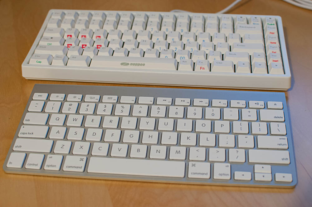
Choc Mini behind the Apple Wireless Keyboard
The physical design is very simple, but nicely executed. As far as I can tell, it doesn’t contain a single screw. The case clips on, so it can be disassembled with nothing more than some stout fingernails.
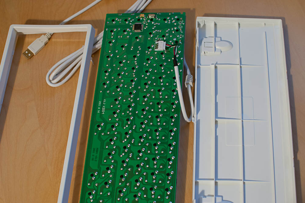
Choc Mini opened up
Aside from the two clamshell halves of the plastic case and the internally-detachable USB cable, there is only the main circuit board with the mounting plate, keyswitches, and electronics. The top of the PC board is populated with just the keyswitches, the key matrix diodes, and jumpers as necessary to allow a single-layer PCB design. You can see the diodes from the side:
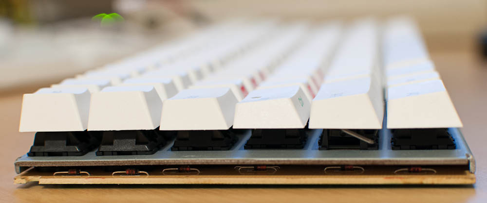
Choc Mini diodes
Electronics: The Switch Matrix and Microcontroller
The diodes’ cathodes are connected to the column traces, so that the matrix circuit looks like this:
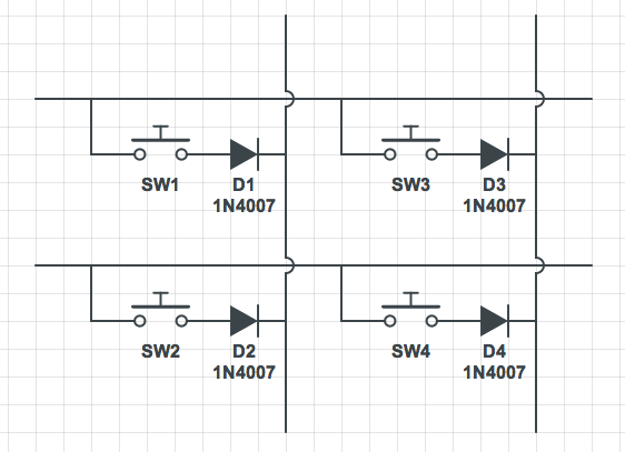
Choc Mini matrix schematic diagram
(They’re not actually 1N4007s; that’s just what Circuitlab gave me.)
The keyboard uses Elan Microelectronics’ EM78M611E microcontroller (specifically, the EM78M611EAAQ).
Many microcontrollers, including the EM78M611E, offer selectable pull-up resistors on their inputs as a convenience. So, this means that to scan the matrix without using any external parts, one must scan the columns, asserting low on each one in turn, and then read the rows to see which keys are pressed. We can’t assert low on each row and read the columns, because of the direction of the diode.
This keyboard has a matrix that’s laid out in about as straightforward a manner as you could imagine, in 6 rows and 16 columns:
Choc Mini matrix map—coming soon
So, that means scanning across all 16 columns, one at a time. On the face of it, that seems like it would take longer than had the diodes been installed in the other direction, but it probably won’t actually matter much, in reality.
It seems like a good idea to observe the rows and columns in operation with an oscilloscope, so I pulled out my trusty Tektronix 2246. I observed the following:
- Rows are uniformly high (3.3 V) with no keys pressed. When a key somewhere on that row is pressed, then there is an almost infinitesimally short low-going pulse at 18.5 ms intervals.
- Columns are uniformly low (0 V) with no keys pressed. When a key somewhere on that column is pressed, then the column goes high, again with a very short low-going pulse at 18.5 ms intervals.
- The point between the keyswitch and the diode looks just like the column, except that it stays low when another key in the same column is pressed; it only goes high with the low-going pulses when that key is pressed.
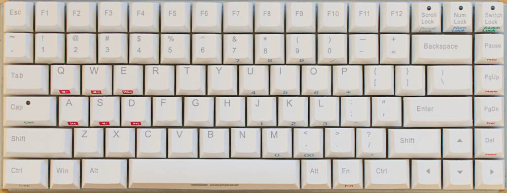
- If more than one key on a row is pressed, then more than one low-going pulse can be seen, spaced about 1.05 ms apart.
Here’s a look at a row trace with six keys on that row pressed at once:
Choc Mini matrix scan pulses
Putting this all together, the controller is, as I expected it had to do, scanning the columns, for each one asserting low to test for pressed keys in that column. The rows are connected to inputs on the microcontroller, and the pull-up resistors are enabled.
It seems that the controller asserts low for a very short amount of time (see the closeup trace, below), and tri-states the output otherwise. It never actually drives the output lines (and thus the columns) high. So, other than for the very short period of time during which it reads the row state, the column is either left low if no keys are pressed, or pulled high by the row-input pull-up resistors when a key is pressed. This probably saves a bit of power. When no keys are pressed (which is most of the time), the columns are left low. The lack of regular high-low-high transitions on the columns neither consumes power nor radiates EMI. Furthermore, when a key is pressed, current is only drawn through the row input pull-up resistors for long enough to test the rows. (Although that wouldn’t change if the columns were driven high at normal state, rather than tri-stated.)
There’s no advantage of switching the state of the row inputs, since at quiescent state, no current will flow through the keyboard matrix at all.
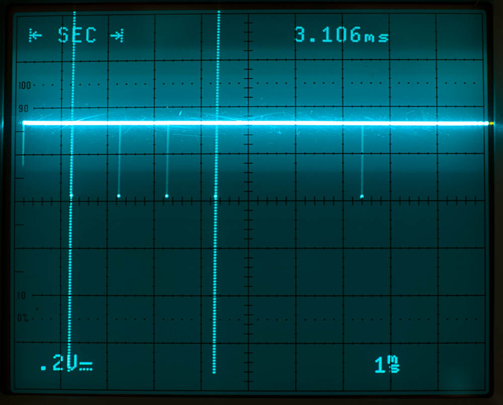
I got as close a look at the low-going pulse of a pressed key being scanned as I could muster. It’s not really feasible to try to measure the pulse duration with this trace; it’s just too short. But the shape of the pulse does seem consistent with the column being driven low, and then the row input pull-up resistor pulling the line back up, fighting whatever stray capacitance there is in the PCB. It’s a really short pulse:
Choc Mini pulse closeup
So, the controller is able to scan the entire matrix every 18.5 ms. It seems to take just a hair over 1 ms to complete a scan of a column and move to the next one, so that leaves another 1.5 ms to initiate sending a USB packet containing the pressed key state. Assuming that it doesn’t take too long for the USB message to be sent to the host, that’s around 20 ms latency for key-presses. That’s pretty reasonable.
USB Electrical Interface
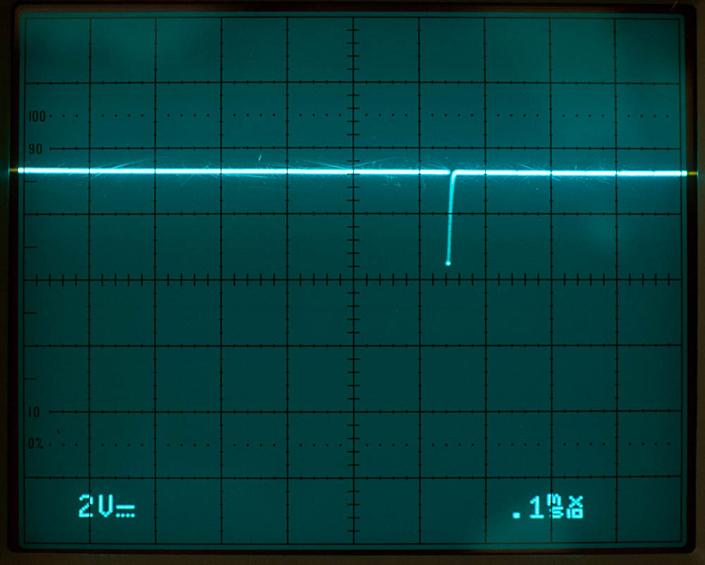
And just for fun, let’s see what the USB data lines look like:
Activity on the idle USB bus with the Choc Mini attached
This shows nicely the NRZI bit sequence at 1.5 Mbps. At that bit rate, there should be a transition (for a 0, or not, for a 1) every 0.666 µs, or two transitions every 1.333 µs. So, the Choc Mini is operating at USB low-speed rate, which is perfectly sensible for a keyboard.
Since I measured this on the D+ line at the keyboard, I assume that the nice, sharp waveform is the keyboard transmitting, and the slightly attenuated and softer-edged waveform superimposed on it is the signal from the computer after the capacitive and resistive effects of a meter of wire. It really doesn’t look bad, considering.
USB Behavior
The USB Human Interface Device (HID) specification defines how devices like keyboards report their configuration to the host computer, so that the host can interpret the data the device returns (in structures called reports). It’s remarkably flexible. For simplicity of implementing embedded operating systems, such as the boot firmware, there is a simple, completely specified Boot report format that a keyboard or mouse should use. Devices are also free to use other, more complex report formats when talking with fully USB-compliant operating environments, like a host OS. These report formats are described by the device’s report descriptors.
The Choc Mini’s USB HID descriptors are a mess. For instance, sequences of data in HID reports can be in one of two formats: Array or Variable. Array items are a sequence of slots for data, where each slot can be filled in with an activated control (such as a pressed key) or be left empty. Variable items are a sequence of some number of bits (often one) for each control, with the value for each control corresponding to the state of the control. The first point in Appendix C: Keyboard Implementation of the HID Spec states:
Non-modifier keys must be reported in Input (Array, Absolute) items. Reports must contain a list of keys currently pressed and not make/break codes (relative data).
The Choc Mini violates this rule by using a series of Variable items, so I suppose we can’t really fault the Mac for not supporting it.
Even worse, the first interface (of two) defined by the Choc Mini describes itself as a Boot Keyboard, but the report format is nothing close to matching the boot report format. I’m not really sure how this works at all, even on Windows or Linux.
The Choc Mini devotes the second interface to handling the Consumer Controls (Play/Pause, Fast Forward, Rewind, etc.), System Controls (System Power Down, Sleep, and Wake Up, although I’m not sure how it might use these), and several more regular keys (F keys, Esc, Backspace, I, punctuation keys, and several others). The order it defines these seems quite random, as well. I don’t really know what was going on in the designer’s minds.
I know that Noppoo chose the Variable bitfield report format so that they could support "n-key rollover," allowing the keyboard to report that any combination of keys on the keyboard are currently pressed—up to and including all of them. It’s not clear to me that anyone will ever need quite that many keys to be pressed at once, though, and it seems like they’ve made quite a compatibility sacrifice in order to achieve it.
The Leopold FC200 manages to attain 18-key rollover while maintaining even Boot keyboard compatibility until you go to the seventh simultaneous key. (I haven’t had a chance to try it, yet, but I suspect Boot-mode environments would just ignore the extra keys pressed.) And the full mode works in every operating environment I’ve tried it on. See the FC200's HID descriptors for details on the method they chose. This seems like a great approach to use.
One last note on the keyboard’s behavior: Neither the Switch Lock nor the Fn key send any report to the host, although, naturally, Num Lock, Caps Lock, and Scroll Lock do. Switch Lock just switches the behavior of the Control and Caps Lock keys within the keyboard, as indicated by its LED state (maintained internally). Fn causes the media control or other alternate usages printed in red on some keys to be sent. On the other hand, after the Num Lock keypress is sent to the host, the host sends back the command to turn the Num Lock LED on. I presume that this is what switches layers within the keyboard such that the letter keys send the (probably Keypad usage) key codes for the correspondingly printed numbers.
PS/2 compatibility
While the Choc Mini fails utterly to work with Macs as a USB keyboard, it does reportedly work when connected through a USB-to-PS/2 adapter and then a PS/2-to-USB converter. I imagine that this is because it doesn’t pull weird tricks in its native PS/2 mode, and the PS/2-to-USB converter also doesn’t try to do anything ridiculous. I suppose n-key rollover would be sacrificed in this mode, but it would still be useable.
All is not perfect, even in PS/2 mode, though. While other PS/2 keyboards work just fine with my DEC VT525, the Choc Mini (through a USB-to-PS/2 adapter) mostly works, but has some quirks. For instance, the shift keys repeat. If I hold down a shift key for more then a second or two, the accessibility mode (activated by pressing Shift five times in a row) is activated.
Next steps
The keyboard matrix has 6 rows and 16 columns. In addition, there are 4 LEDs. That’s a total of 6 + 16 + 4 = 26 I/O lines required. That helps put constraints on the microcontroller that will be required to handle this keyboard.
I think this is about as far as I can go before the destructive operations.
The easiest way to replace the microcontroller would be to desolder it from the PCB and run wires to a separate break-out board for my new microcontroller. I say easy as if desoldering a QFP-44 without damaging the solder pads will be trivial. It won’t, but I have some thoughts.
I’ll also need to fit the new controller inside the case, but it looks like there’s plenty of room. More on that in the next section.